SWP-P
Horizontal Rotary Turntables
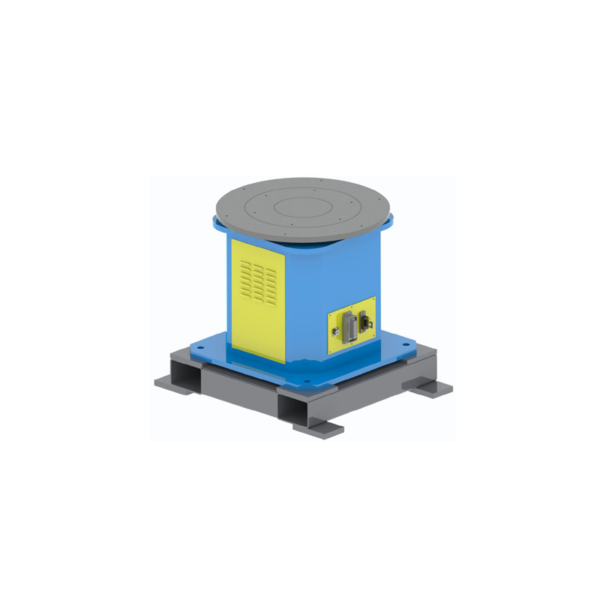
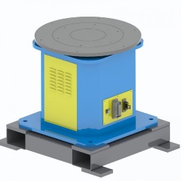
The workpiece sits on a horizontal tabletop for one-axis rotation.
Rated payload options: 300 / 500 kg
Custom configurations available
View series details →
Standard series + custom configurations
Compare 1, 2 and 3-axis positioner families, then match the configuration to your workpiece, fixture, center of gravity, motion and cell layout. EVST offers standard series and custom configurations after technical review.
What it is
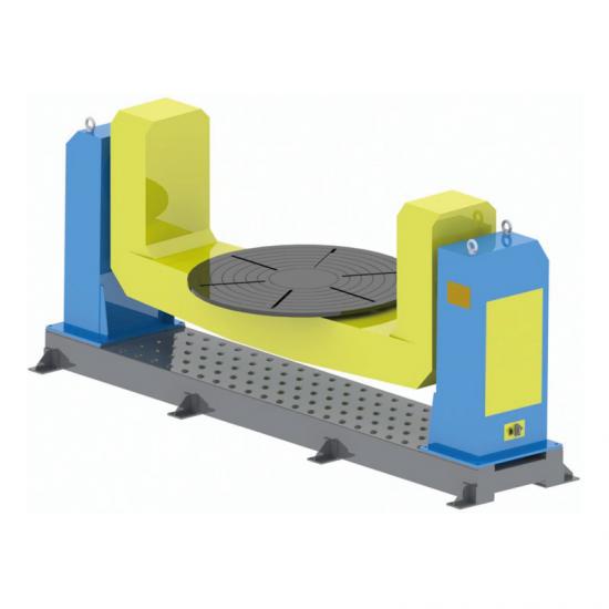
A robotic welding positioner is a servo-driven external axis that holds and reorients a workpiece for welding access. Unlike a simple rotating table, it may combine rotation, tilt or exchange motion. Turning rolls support cylindrical vessels by friction; positioners secure the workpiece to purpose-designed tooling.
Nine product series
The rated-payload options below support an initial family comparison. Rated payload means the combined weight of the workpiece and fixture; final selection also depends on center of gravity, dimensions, motion and cell conditions. Custom configurations are available for every series after technical review.
For a single rotary motion or headstock-tailstock support
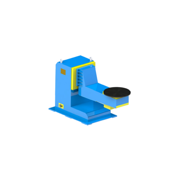
SWP-P
The workpiece sits on a horizontal tabletop for one-axis rotation.
Rated payload options: 300 / 500 kg
Custom configurations available
View series details →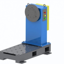
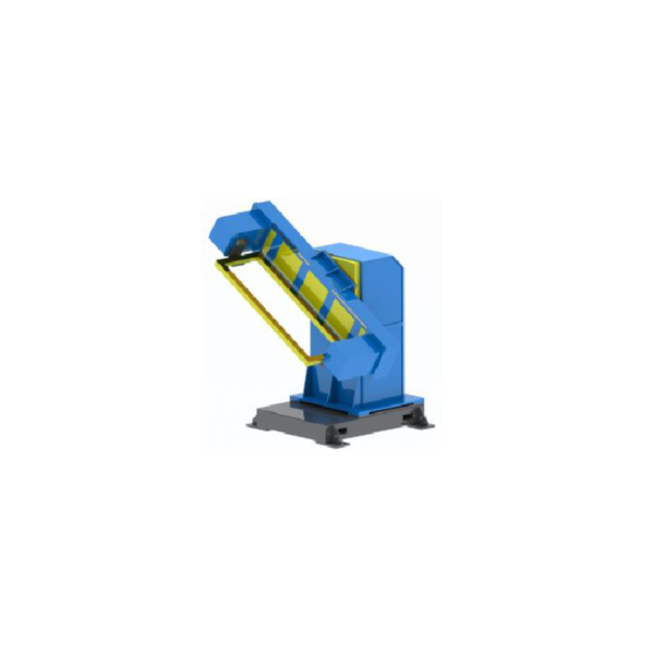
SWP-Z
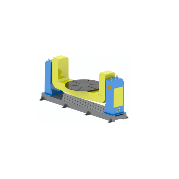
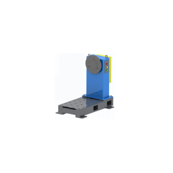
The fixture bolts to a vertical spindle faceplate and rotates about a horizontal axis.
Rated payload options: 300 / 500 kg
Custom configurations available
View series details →
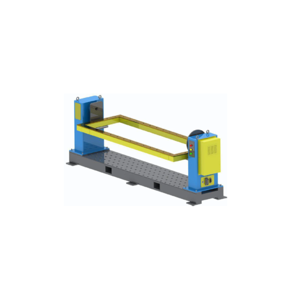
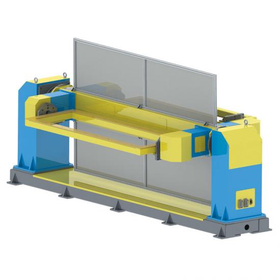
SWP-ZW
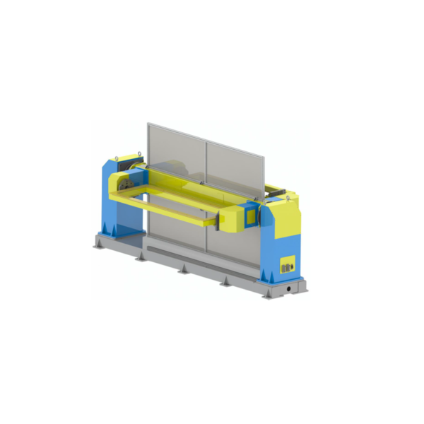
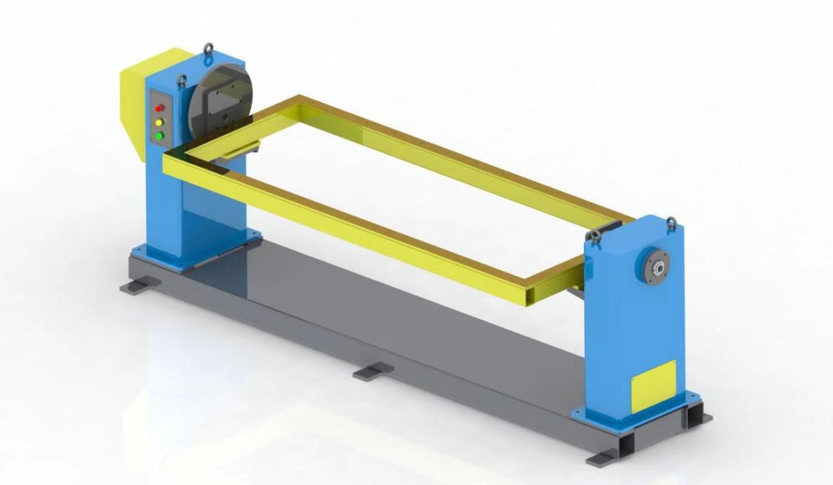
Supports longer fixtures or frames between a driven headstock and tailstock for horizontal-axis rotation.
Rated payload options: 300 / 500 / 800 / 1,200 kg
Custom configurations available
View series details →Combines rotation and tilt to improve seam orientation and access
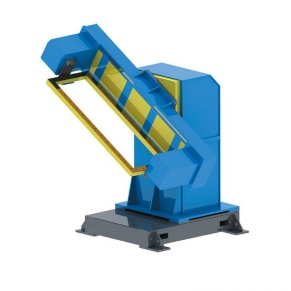
DWP-C
An open side supports loading access around the tooling.
Rated payload options: 200 / 500 / 1,000 kg
Custom configurations available
View series details →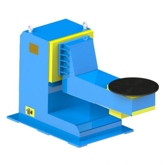
DWP-L
The offset L-type frame leaves approach space around the fixture for the robot.
Rated payload options: 500 / 1,000 / 2,000 kg
Custom configurations available
View series details →
DWP-U
Two upright supports carry a centered larger fixture or structural part through rotation and tilt.
Rated payload options: 1,000 / 3,000 / 5,000 kg
Custom configurations available
View series details →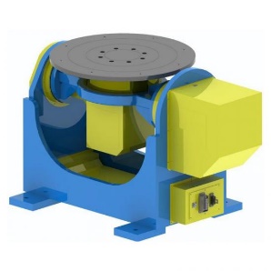
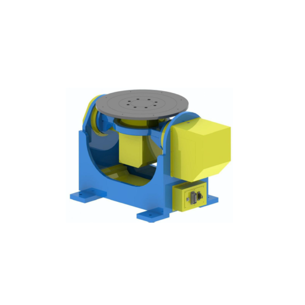
DWP-P
A platform-mounted fixture rotates and tilts as one assembly.
Rated payload options: 300 / 500 / 1,000 kg
Custom configurations available
View series details →Adds station indexing or exchange motion; cell layout is confirmed per project
TWP-C
Vertical station indexing changes work position while the positioner orients each part for welding.
Rated payload options: 500 / 1,000 kg
Custom configurations available
View series details →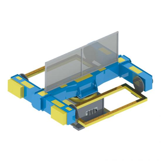
TWP-S
Horizontal station indexing presents alternating load and weld positions.
Rated payload options: 500 / 1,000 kg
Custom configurations available
View series details →Light selection
You do not need a finished specification to begin. These inputs are enough to screen the product family; use the separate guide for deeper selection work.
Describe whether the workpiece needs rotation, tilt, station indexing or exchange motion.
Provide the combined workpiece-and-fixture weight and the center-of-gravity position relative to the axes.
Share the workpiece envelope, fixture mounting method, interfaces and loading requirements.
Provide the robot position, weld access, operator path, safety clearance and station sequence.
Provide the robot make/model and the required coordinated motion, controls and site interfaces.
For a fuller comparison of axis count, L/C/U layouts and selection inputs, read the Welding Positioner Guide.
Standard series establish the starting point; final interfaces and layout are confirmed per project.
Customization and integration
When a positioner operates as a robot external axis, mechanical interfaces, motion, control boundaries and safety planning must be reviewed with the robot and cell. Custom configurations are confirmed after the project inputs are defined.
Confirmed from the workpiece, fixture and loading method.
Defined from weld access and the station sequence.
Robot model and control requirements are checked during technical review.
Layout, operator access and guarding needs belong in the cell plan.
Applications
These are typical applications, not fixed configurations. The series, rated payload and tooling still need to be selected from the actual workpiece and cell.
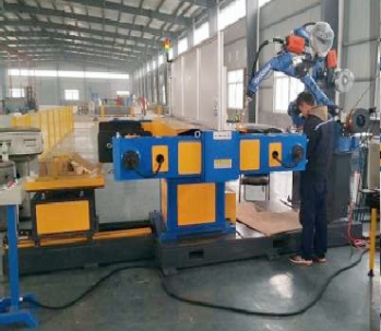
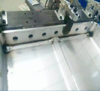
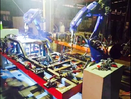
Use controlled rotation to bring circumferential seams into the robot’s working envelope.
Headstock-tailstock layouts can support longer fixtures between two ends.
Combine rotation and tilt to improve approach angles for different seams.
Select a single- or multi-axis concept from the fixture, center of gravity and robot layout.
Reorient multiple weld faces to more suitable positions within the cell.
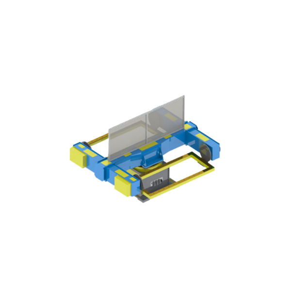
Three-axis station-indexing layouts can start a multi-station concept; the final arrangement is project-specific.
Why EVST
From project inputs and series selection to production-stage checks, the exact configuration and acceptance requirements remain project-specific.
Workpiece, fixture, total weight, center of gravity, motion and cell conditions are reviewed before the final configuration is confirmed.
Process checks at key production stages help identify issues before delivery.
Machining resources support dimensional control for mounting surfaces, holes and rotary interfaces.
Structural components undergo annealing to reduce residual stress and support dimensional stability.
Frequently asked questions
It is a controlled external axis that holds and reorients a workpiece so the robot can access weld seams. The required axis count depends on the workpiece motion and cell layout.
On this category page, rated payload means the combined weight of the workpiece and fixture, not the workpiece alone. Final selection also requires review of center of gravity, dimensions and dynamic conditions.
A single axis provides one rotary motion; two axes add tilt; three axes can add station indexing or exchange. Base the choice on weld access and the station sequence. Read the Welding Positioner Guide for the fuller comparison.
The letters describe the general structure around the supports and tooling. Selection depends on workpiece size, fixture, loading space, robot approach and required rated payload. Compare the layouts in the Welding Positioner Guide.
Consider it when a longer fixture or frame needs support between two ends and rotation around a horizontal axis. Support spacing and interfaces must be confirmed from the workpiece. See the Welding Positioner Guide for more selection context.
The same total weight can create different conditions for the axes and structure when its center of gravity changes. Weight alone is therefore not enough for final selection.
Custom configurations are available after technical review. Provide the robot make/model, workpiece and fixture data, required motion, cell layout and interface needs so the suitable configuration can be confirmed.